NOTE: Sections 1 - 3 describe our work up until Friday 05/19. Sections 4 and 5 describe changes made to our project on Saturday and Sunday.
In this project, we were tasked with implementing progressive meshes. Progressive meshes allow us to simplify (and revert) the complexity of meshes at runtime, allowing for the general shape to be preserved but at a much lower computational cost due to the reduced face count. While there is no point in doing this when an object is up close, it is particularly useful to reduce the meshes of objects when they are very far away, where one cannot observe miniscule fine details.
In this blog post, we will explain the workings behind our implementation. The Windows executable (along with necessary .dll files) can be downloaded here.
Usage: mesh <relative-path-to-OFF-file>
Controls:


0. Project intro
In this project, we were tasked with implementing progressive meshes. Progressive meshes allow us to simplify (and revert) the complexity of meshes at runtime, allowing for the general shape to be preserved but at a much lower computational cost due to the reduced face count. While there is no point in doing this when an object is up close, it is particularly useful to reduce the meshes of objects when they are very far away, where one cannot observe miniscule fine details.
In this blog post, we will explain the workings behind our implementation. The Windows executable (along with necessary .dll files) can be downloaded here.
Usage: mesh <relative-path-to-OFF-file>
Controls:
- Press M to toggle between viewing the model and wireframe
- Press Esc to terminate the program
- Press and hold - (minus key) to remove an edge
- Press and hold P to undo the most recent edge removal on the mesh (until there are no more removals to undo)
1. Mesh Viewer
In order to visually verify that our implementation works, a basic mesh viewer is necessary.
As the mesh is read in from an .off file, the minimum and maximum x, y, and z coordinates of the mesh are tracked. When the read is complete, we are able to determine the average of the x, y, and z coordinates as half the sum of the min and max, and shifted the mesh by the negative amount so as to nicely center it on the screen. Using the same min and max values, we are also able to determine the longest dimension as the max of the differences between the x, y, and z dimensions, and scaled the model down by that longest dimension. This guarantees that the mesh would fit inside an imaginary 1 x 1 x 1 box. The camera is placed twice as far away, so that the model takes up about half the screen. The mouse can be dragged to rotate the camera around.
Very basic coloring is used for the model. Since the model is centered and has all dimensions between -1 and 1, we simply used the vertex positions as colors, mapping -1 in the x/y/z to 0 in r/g/b, and +1 in x/y/z to r/g/b. The same rgb color is also used as a fake normal, with several weak lights shining at the mesh to highlight a couple of areas where one would not be able to visually see the detail of. Below are a few samples of the basic mesh viewer:


2. Mesh Data and Decimation
As the .off file is read in, we keep track of 2 things: the list of vertices that are connected to a vertex, i.e. the vertices that show up in the same face as another vertex, and the faces a vertex is part of.
When a particular edge (v0, v1) is removed, we perform the following updates:
- Go through the list of neighbors of v0 (vertices connected to it), then remove v0 from the neighbor lists of v0's neighbors.
- Do the same thing for neighbors of v1.
- Go through the list of faces involving v0 and mark them unused. At the same time, push the other 2 vertices that form the face into a temporary vector. If any of the faces have v1 in it, then we don't push that (as it will be degenerate).
- Do the same thing for faces involving v1.
- Add a new vertex that is the midpoint of v0 and v1 - call it m.
- Go through the vectors of vertex pairs that formed the faces involving v0 and v1, and create a new face with m and such pair.
- Update the list of neighbors and faces of each of the 3 vertices in that face accordingly.

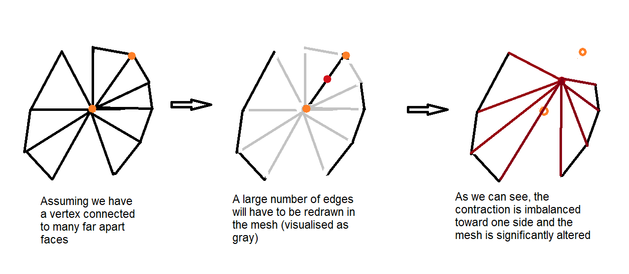
However, currently the vertices position is only set to the midpoint of the edge containing both vertices being contracted, and so the decimation is imbalanced and does not properly reduce the mesh. For instance:

3. Quadric Error
Once all vertices are read in, the quadratic matrix Q is derived for every vertex in the model. Since a list of faces that a vertex V belongs to is maintained, it is very easy to obtain the planes that intersect at V. The Q matrix is calculated as the sum of all K matrices as in section 5.1 of the Garland paper.
Additionally, since we also keep track of every vertex connected to V by an edge, we can determine the quadric error to be the sum of the Q matrices for each pair (V, V') where V and V' are connected by an edge. Each of these errors are stored in 2 places:
- A map, with the edge (V, V') as the key, and the error as the value for this key.
- A priority queue containing a pair <error, edge>, sorted by the value of error, so that we can quickly find the next edge to remove so as to minimize the error.
Unfortunately, removal of edges is currently a one-way process; we have not yet been able to reverse this process yet. Current considerations on how to do this are as follows:
- Maintain a vector indicating which vertices and faces were removed, and which vertex and faces were added at each step (this causes very high memory usage), or
- Write the above information to a file (this causes slow performance due to file I/O).
The following are (problematic) illustrations of a few models and partial decimations of their meshes. Note how certain "regions" of the model have long edges connecting them to another region. Also note how holes mysteriously appear. It will be fixed on Saturday and Sunday (hopefully):


4. Changes since Friday
To correct issues as described above, the following overhaul was done on Saturday and Sunday:
- No deletions are ever made to the list of faces that the mesh uses - only additions are done as new vertices are added as a result of mesh decimation. To indicate whether or not a face should show up in the on-screen mesh, a boolean flag is used.
- This allows us to undo edge removals, simply by flipping boolean flags (described in part 5)
- While storing a list of faces through time seems inefficient, the face data only needs to be bound to the shaders once when an edge removal occurs - no computations are needed for subsequent draw calls since all the data has already been bound to the vertex buffer object (VBO) and the VBO remains unchanged.
- Mesh decimation and error determining follow the same process as above, with the exception of where the new vertex appears. The following linear process is now applied:
- Consider the edge (v0, v1): assume that at time t = 0, we are at v0, and at time t = 1, we are at v1.
- Lerp (Linear interpolate) an intermediate point between v0 and v1 for 51 different timesteps of t (t goes from 0.0 to 1.0, increasing by 0.02 each time)
- For all such points, the quadric matrix is always the sum of the two Q matrices that correspond to v0 and v1, so we perform the same multiplication as normal
- The selected point V' is the one that produces the smallest error value
- This is essentially a calculation where the vertices are weighted by the volume of the faces it belongs to (disregarding degenerate triangles)
- If a vertex has more volume associated with it, the new vertex will appear much closer to it (as illustrated below)
- This linear process is also applied when calculating the error for each edge (v0, v1) in preparation for potential future removals.
- This process addresses the issue as described in section 2, however one remaining issue stems from the removal of a long edge (comparison with Friday's implementation shown in green):


- The underlying data structure for edges and their associated error is now changed to an unordered list (that is, insertions are done in O(1) time since we don't enforce any ordering yet)
- We take advantage of std::sort to sort through this list every time all additions are completed (i.e. after the .OFF file is read in, or after all the faces and edges are reassigned following an edge collapse).
- The sorting of this list allows us to also determine in O(1) time which edge to remove.
- Since vertex additions add and change a relatively small number of edges in comparison to the size of the list, resorting it takes essentially linear time, since most of the list is already sorted from the previous iteration. This effectively also lowers the computational time, as we do not need to rebuild a priority queue after each edge removal.
- Due to the removal of the map and priority queue (of which both also have their own internal storage structure that takes up quite a bit of memory) in favor of an unordered list, memory usage for mapping edges to their errors is halved. On the largest model (brain.off), this effectively lowers the memory usage of the program by about 25MB (which is not quite that significant nowadays but the more memory saved, the better).


Improved Mug - The Curved surface of the mug stays intact for far longer.


Remaining issues
- Error computation is not entirely correct, still - this can be seen in the above illustrations, where shorter edges seem to be ignored.
- We suspect that this could be because of the size reduction of the model (in order for it to perfectly fit on the mesh viewer) causing floating point calculation inaccuracies, due to numbers being even closer to 0.
- It could also be that vertices closer to the "center" of the model produce a smaller calculated error, due to forceful re-centering of the mesh when trying to fit it in the viewer
- However, no bizarre cross edges or "merging" of regions of the model appear anymore, due to proper weighting when considering the new vertex for an edge removal - note how the cow looks somewhat "better" now since it no longer has missing limbs, nor does it have strange lines connecting the limbs/face with the center of its body
5. Geomorphs
The user must manually hold down the minus or P key to interactively remove/recover edges. We probably could have made an automated way to do this without requiring the user to hold one finger in the same place, but we have no idea why we didn't think of this prior to the submission due date.
In any such case, the following change was made in order to make this possible:
- After every edge collapse, a list of faces that got added and removed are kept in memory
- When a recover() command is issued, the last list that was added will be undone, i.e. faces that got added will be removed, and faces that got removed will be added, and the index in the list of face changes is decreased
- Note: the underlying list of faces does not get modified in any way - we are using boolean flags to indicate whether a face should show up in the rendering of the mesh or not
- When an edge collapse command is issued, if the index in the list of face changes is less than the length of the list, this means that a prior recover() command was issued, in which case we simply need to flip the boolean flags back. Else, that means there are no recoveries to undo, and we go through the regular mesh decimation algorithm again.
The following half-minute video demonstrates the simplification (which currently still not entirely accurate, as mentioned above) of a torus and the reconstruction of it:
No comments:
Post a Comment